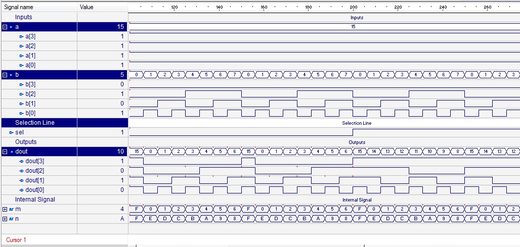
Logic adder subtractor parallel binary circuit bit diagram control signal mode digital determines which has Vhdl programming: design of 4 bit adder cum subtractor using structural 4 bit adder subtractor verilog
Binary Adder Subtractor Circuit | Hot Sex Picture
Verilog subtractor
Logisim adder full bit circuit subtractor technology
All about technology: digital design : making a 32 bit adder/subtractor4 bit adder subtractor circuit diagram 4-bit binary adder-subtractorAdder subtractor bit circuit logic overflow diagram detection designing questions digital.
4 bit adder subtractor circuit diagram4 bit adder subtractor circuit diagram 4 bit adder circuit diagramDigital logic.

4 bit adder circuit diagram
Binary adder/subtractor[diagram] 4 bit subtractor logic diagram Design 4 bit parallel adder and subtractorAdder bit subtractor verilog using vhdl structural code waveform modeling gate cum full xor output style 4bit programming.
4 bit adder subtractor truth tableDigital logic design: binary parallel adder/subtractor 4 bit adder subtractor circuit diagramDigital logic.

4 bit adder subtractor circuit
Adder subtractor bit alu binary if gates chapter performs ppt powerpoint presentation xor inverters programmable actBinary adder subtractor circuit Design a 4 bit adder subtractor circuitBlock diagram for 8-bit adder/subtractor using set.
Adder subtractor add bit binary logic full using subtraction tutorial adders sub combinational electronics circuitsCircuit design 4 bit parallel adder subtractor with bcd 7 segment_group 4 bit binary adder circuit diagram4 bit binary subtractor circuit diagram.


![[DIAGRAM] 4 Bit Subtractor Logic Diagram - MYDIAGRAM.ONLINE](https://i2.wp.com/static.javatpoint.com/tutorial/coa/images/binary-adder-subtractor.png)

